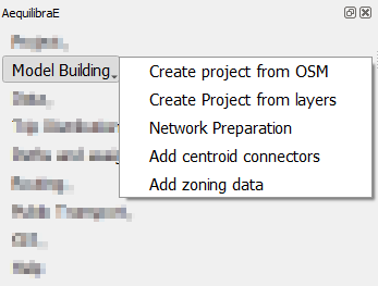
Model building#
On the Model building tab, it is possible to effectively build an AequilibraE model, and to do so, there are some options, such as creating project from Open Street Maps or using your existing layers.
In this tab, you can also add centroids and zones to your project.
Create project from OSM#
The first feature is the capability of importing networks directly from Open Street Maps into AequilibraE’s efficient TranspoNet format. This is also time to give a HUGE shout out to Geoff Boeing, creator of the widely used Python package OSMNx. For several weeks I worked with Geoff in refactoring the entire OSMNx code base so I could include it as a submodule or dependency for AequilibraE, but its deep integration with GeoPandas and all the packages it depends on (Pandas, Shapely, Fiona, RTree, etc.), means that we would have to rebuild OSMNx from the ground up in order to use it with AequilibraE within QGIS, since its Windows distribution does not include all those dependencies.
For this reason, I have ported some of Geoff’s code into AequilibraE (modifications were quite heavy, however), and was ultimately able to bring this feature to life.
Note
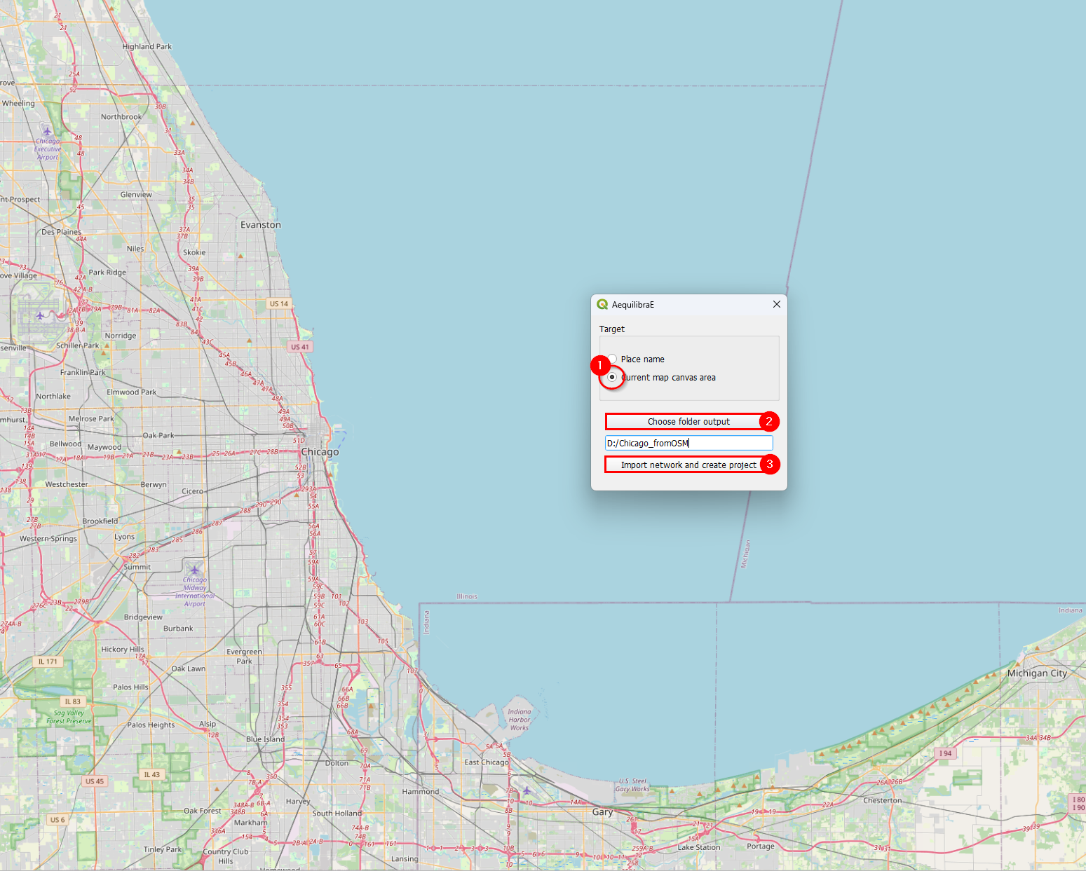
Importing networks from OSM is a rather slow process, so we recommend that you carefully choose the area you are downloading it for. We have also inserted small pauses between successive downloads to not put too much pressure on the OSM servers. So be patient!!
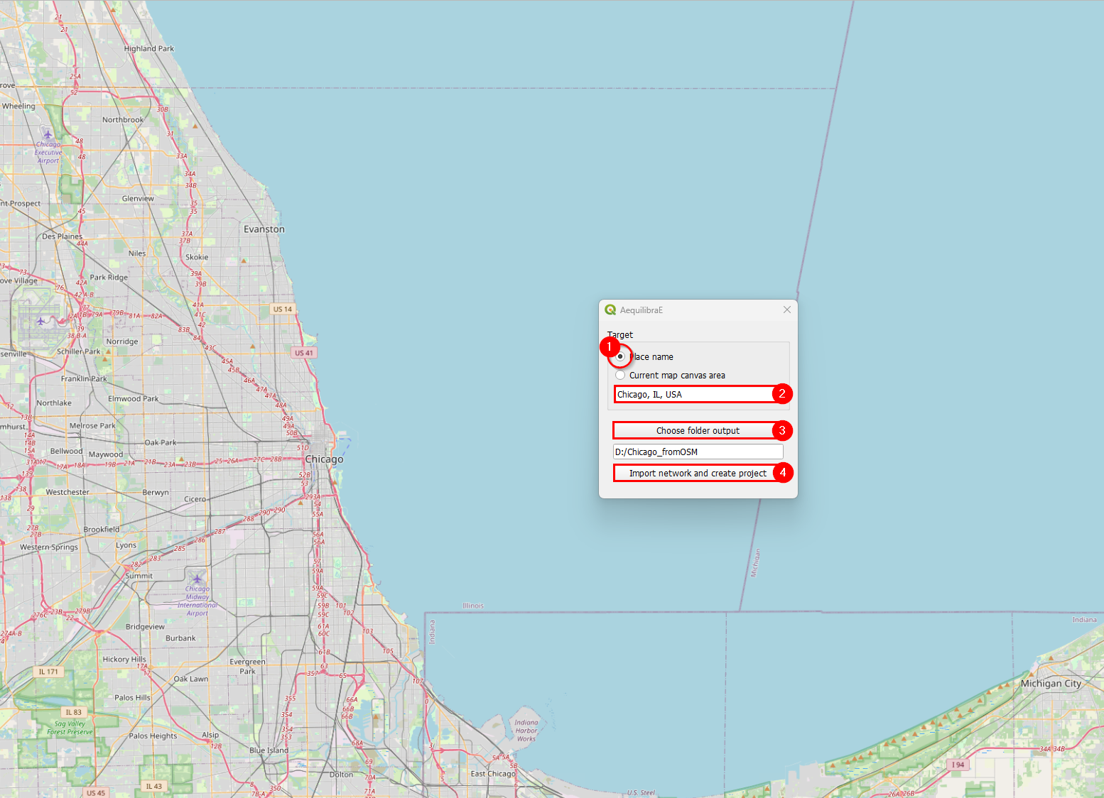
Importing networks from OSM can be done by choosing an area for download, defined as the current map canvas on QGIS…
… or for a named place.
Project from layers#
The AequilibraE project can also be bootstrapped from existing line and node layers obtained from any other source, as long as they contain the following required field for the conversion:
Link ID
a_node
b_node
Link direction
Length
Speed
Allowed modes
Link Type
These requirements often create quite a bit of manual work, as most networks available do not have complete (or reliable) information. Manually editing the networks might be necessary, which is common practice in transport modelling.
Before creating a project from the layer, you can understand how to prepare the layers for this task on the page Preparing a network.
After all field preparation is done, one can import those layers into an AequilibraE project using a dedicated tool in the Model building menu in AequilibraE.
Accessing Model building > Create Project from Layers, the user is presented with the following screen.
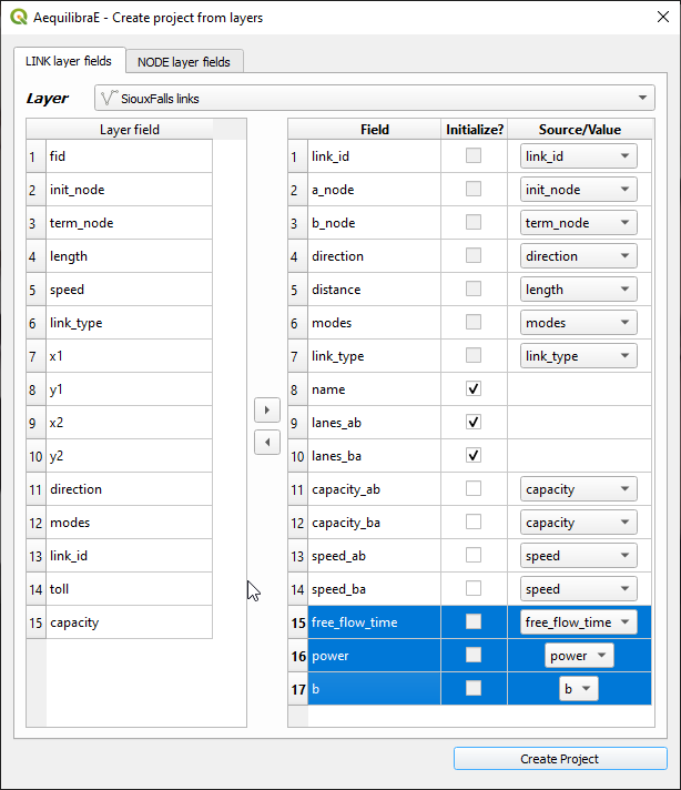
The first 7 fields for links are mandatory, and one needs to associate the corresponding layer fields to the network fields.
The other fields that will be listed on the left side come from the parameters file (see the manual for that portion for more details), but the user can add more fields from the layer, as all of them are listed on the left side of the screen
In the case of the nodes layer, only two fields are mandatory.
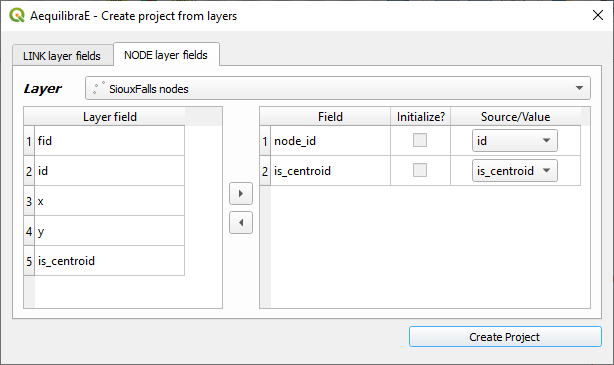
After filling all fields, it is just a matter of saving it!
After running this tool a sqlite file (spatialite enabled) will be created and you can edit the network (create, move or delete links and nodes) and both layers (including node ID and A_Node/B_Node fields) will remain consistent with each other.
Network preparation#
When preparing your project network, you might face there are two distinct situations:
User has only the network links: This is the case when one exports only links from a transportation package or downloads a link layer from Open Street Maps or a government open data portal and want to use such network for path computation. This tool then does the following:
Duplicates the pre-existing network in order to edit it without risk of data corruption
Creates nodes at the extremities of all links in the network (no duplicate nodes at the same latitude/longitude)
Adds the fields a_node and b_node to the new link layer, and populate them with the IDs generated for the nodes layer
User has the network links and nodes but no database field linking them: In case one has both the complete sets of nodes and links and nodes for a certain network (commercial packages would allow you to export them separately), you can use this tool to associate those links and nodes (if that information was not exported from the package). In that case, the steps would be the following:
Duplicates the pre-existing network in order to edit it without risk of data corruption
Checks if the nodes provided cover both extremities of all links from the layer provided. Node IDs are also checked for uniqueness
Adds the fields a_node and b_node to the new link layer, and populate them with the IDs chosen among the fields from the nodes layer
The GUI for these two processes can be accessed in the AequilibraE menu Model Building > Network Preparation, and it looks like this:
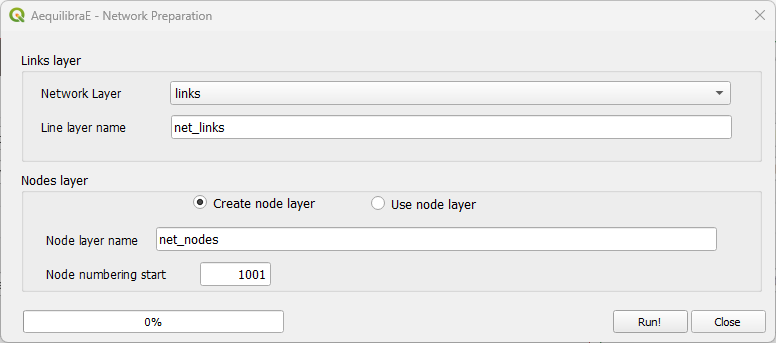
In this case we chose to add nodes with IDs starting in 1,001, as we will reserve all nodes from 1 to 1,000 for centroids, external stations and other special uses (we are not planning to use all that range and that is not necessary, but the numbering gets quite neat that way).
Adding centroids#
Starting in version 0.6 of AequilibraE, centroid connectors can now only be added to AequilibraE projects, and no longer generates new layers during the process.
Before we describe what this tool can do for you, however, let’s just remember that there is a virtually unlimited number of things that can go awfully wrong when we edit networks with automated procedures, and we highly recommend that you BACKUP YOUR DATA prior to running this procedure and that you inspect the results of this tool CAREFULLY.
The GUI for this procedure is fairly straightforward, as shown below.
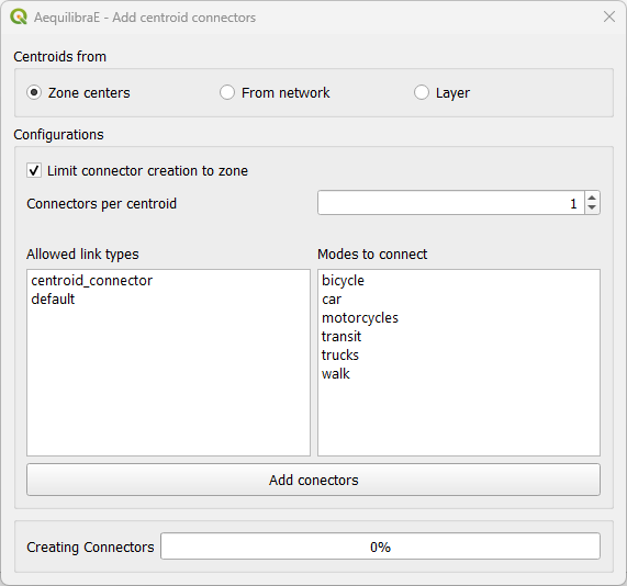
When creating centroids from zone centers, one can choose to limit the connector to the zone or not. Plase notice if one choose to limit the connector creation to a zone that has fewer nodes connected to links of the required types than the number of connectors will result in fewer connectors being created than desired.
One would notice that nowhere in the GUI one can indicate which modes they want to see the network connected for or how to control how many connectors per mode will be created. Although it could be implemented, such a solution would be convoluted and there is probably no good reason to do so.
Instead, we have chosen to develop the procedure with the following criteria:
All modes will be connected to links where those modes are allowed.
When considering number of connectors per centroid, there is no guarantee that each and every mode will have that number of connectors. If a particular mode is only available rather far from the centroid, it is likely that a single connector to that mode will be created for that centroid
When considering the maximum length of connectors, the GUI returns to the user the list of centroids/modes that could not be connected.
Notice that in order to add centroids and their connectors to the network, we need to create the set of centroids we want to add to the network in a separate layer and to have a field that contains unique centroid IDs. These IDs also cannot exist in the set of node IDs that are already part of the map.
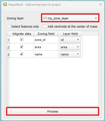
Add zoning data#
It is possible to import to AequilibraE project your own zoning system in case you already have one. Currently, AequilibraE only supports one projection system, which is the EPSG:4326 (WGS84), so make sure your zone layer is in this projection.
To add your zones to the active project, go to Model building > Add zoning data, select the zoning layer you want to add to the project, select weather you want to migrate the data and the respective layer field in the zoning layer, and finally click on process.